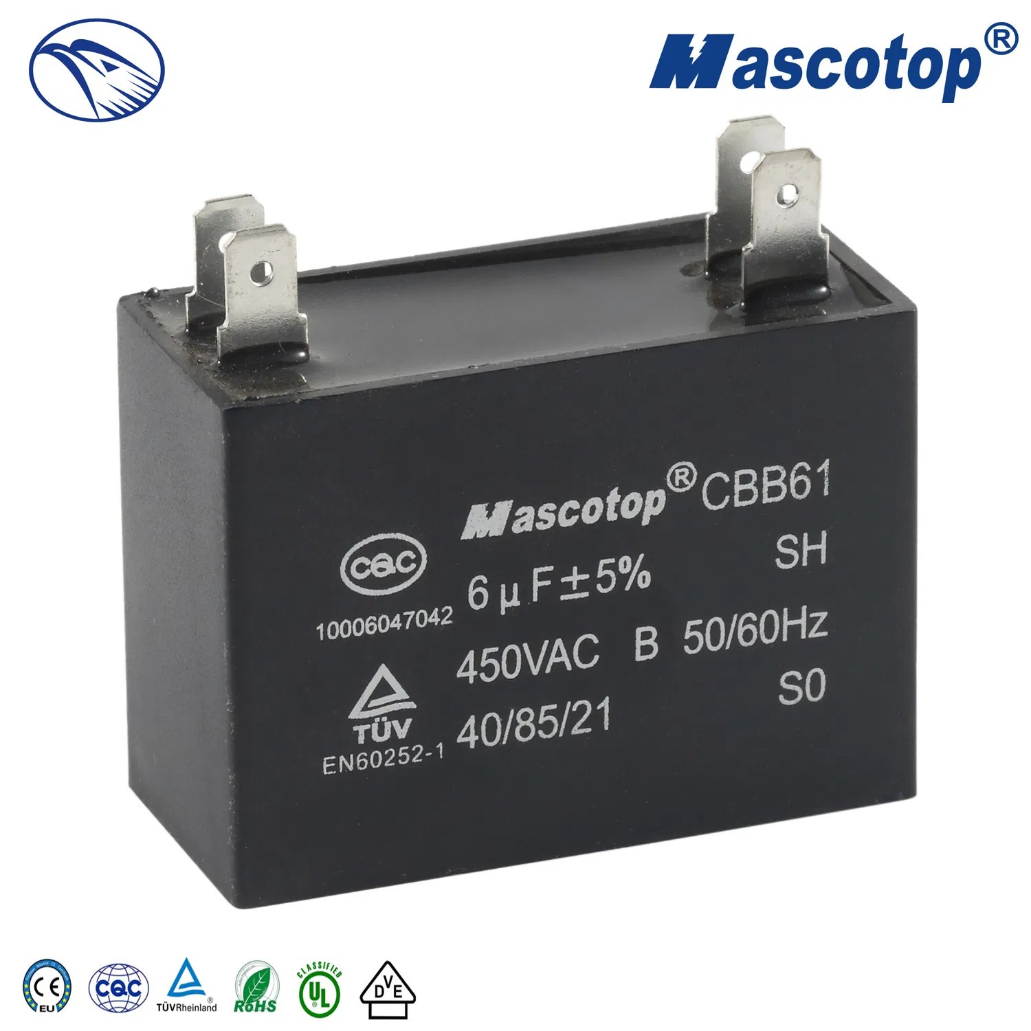
Exhaust fan wiring diagrams with capacitors are essential tools for electricians and do-it-yourselfers alike. Without the correct wiring diagrams, it is virtually impossible to correctly install an exhaust fan, or any other type of electrical device. While the wiring diagrams can appear confusing, with a few basic guidelines, anyone can learn how to read them, and understand what they mean.
Knowing how to interpret an exhaust fan wiring diagram with capacitor is important for any electrician or home improvement enthusiast. Not only does it help you to install the fan correctly, but it also ensures that the fan operates safely and efficiently. In this article, we will go over the basics of exhaust fan wiring diagrams with capacitor, and how to read them to ensure that your fan is installed properly.
First, it is important to understand the components of an exhaust fan wiring diagram with capacitor. A typical diagram will include a ground wire, power wire, switch wire, and a capacitor. The ground wire serves as a safety measure in case the fan shorts out and an electrical fault occurs. The power wire supplies the power to the fan, while the switch wire enables you to turn the fan on and off. Finally, the capacitor helps to ensure that the fan runs at the correct speed and is not overloaded.
Once you understand the components of a wiring diagram, you can start interpreting the diagram. Start by looking at the switch wire. This is the wire that turns the fan on and off. The diagram should show you which color wire corresponds to which terminal on the switch. In most cases, the power wire is the same color as the switch wire.
Next, look at the power wire. This is the wire that supplies the power to the fan. The diagram should indicate which color wire corresponds to which terminal on the power source. Remember that the power source can either be the breaker panel, the wall outlet, or some other source.
Finally, look at the capacitor. This is the component that helps to regulate the speed of the fan. The diagram should indicate which color wire corresponds to which terminal on the capacitor. It is important to note that the capacitor should be connected to the power wire, not the switch wire, as this could cause an overload and potentially damage the fan.
Now that you understand the components of an exhaust fan wiring diagram with capacitor, you can use it to install your fan correctly and safely. Remember to follow all safety guidelines, including using the appropriate circuit breaker and making sure that all of the wires are properly connected. By taking the time to read and understand the wiring diagram, you can ensure that your fan is installed correctly and safely.

China Cbb61 Hot 10uf 450v Ceiling Fan Wiring Diagram Capacitor Ul

Capacitor Cbb61 450v2uf Fan Exhaust Capacitance Capacitors 2uf

4 Wire Cooler Motor Wiring Diagram And Connection Procedure Etechnog
Axial Flow Fan

4 Way Light Single Switch Fan Roughed In Already Can I With Diagram Doityourself Com Community Forums

Hvac Start And Run Capacitor Explained Replacement How To

Motor Winding Connection Diagram All
Indo Tech Electrical Exhaust Fan Reverse Connection Forward Using Capacitor Facebook By Battery Light Home Listrik Switch House

มอเตอร ไฟฟ า 220v 1 Hp ราคาถ ก ซ อออนไลน ท ค 2022 Lazada Co Th

4 Wire Cooler Motor Wiring Diagram And Connection Procedure Etechnog
Ceiling Fan Motor Run Capacitor 1 2uf 450vac 50 60hz Cbb61 Best For Wall Stand Exhaust Everything Else Others On Carou

5 Wire Ceiling Fan Motor Cbb61 8uf 9uf 250vac 50 60hz Polypropylene Capacitor Manufacturers Factory Made In China Jiayang
Mian Electric Exhaust Fan Connection With Two Way Switch 3 Wire Facebook By

Cbb61 Ceilling Fan Capacitor Id 9390608 China Ec21
Ceiling Fan Light Kit Wiring Diagrams Do It Yourself Help Com
Cooler Motor Connection With Capacitor Repair

Cbb61 10uf Ceiling Fan Wiring Diagram Ul Capacitor China Made In Com

Cooler Motor Connection With Regulator Multi Sd


