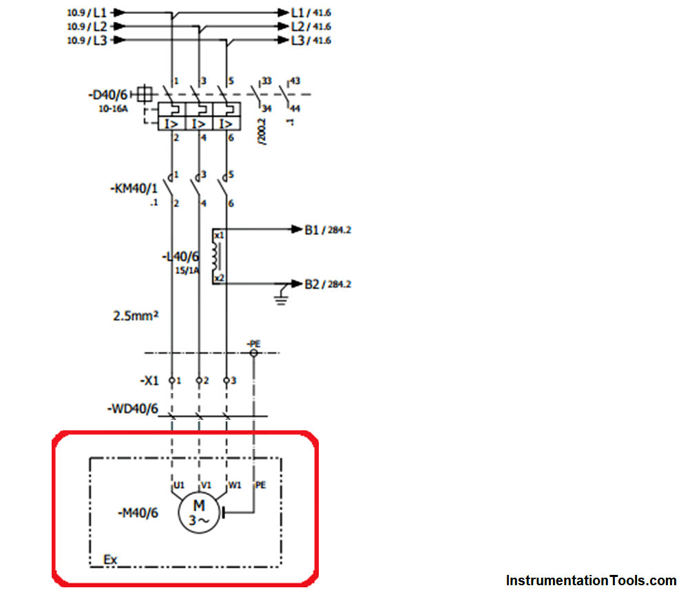
Understanding electrical schematics can be a daunting task for anyone, regardless of technical skill level. It's a complex language that can only be decoded by understanding the symbols and components used in creating them. With a little bit of knowledge, however, even the most novice of technicians can learn to interpret electrical schematic diagrams and use them to their advantage.
The first step to understanding electrical schematic diagrams is to become familiar with the symbols used in the diagrams. These symbols represent various components of the system, such as resistors, capacitors, inductors, transistors, and diodes. Each of these components play an important role in the overall functioning of the system, so it's important to understand what each symbol represents. Once you've familiarized yourself with the symbols, the next step is to understand how the components are connected to one another. This is done by studying the lines that connect the various components.
These lines indicate which parts of the system are connected to each other. Each component will have at least one line connecting it to another component. By studying the lines, you can gain insight into how the system as a whole functions, as well as how different components interact with one another. In addition to the lines, you should also take note of the arrows that appear on the lines. These arrows show the direction of current flow in the system, and help you visualize how the system works.
Once you've familiarized yourself with the symbols and lines used in electrical schematic diagrams, you'll be able to start putting together a basic understanding of the system. The next step is to get a more detailed look at the system. To do this, you'll want to begin studying the component values that are represented in the diagram. Each component will have a numerical value printed next to it, which indicates the amount of current or voltage that flows through it when the system is in use. By studying these values, you can gain a better understanding of how the system will react to different types of inputs.
Finally, you'll need to study the various connections between the components. This is done by looking at the patterns formed by the lines in the diagram. You'll be able to see how different components are connected to one another, as well as which components are sharing the same power source. This will give you an even more detailed look at the system and how it works.
By understanding electrical schematic diagrams, you'll be able to more easily diagnose problems in a system, as well as design new systems from scratch. With a bit of practice and study, anyone can become proficient in reading and interpreting electrical schematic diagrams.

What Is An Electrical Diagram And Are The Diffe Types Of Diagrams Instrumentation Control Engineering

The Schematic Diagram A Basic Element Of Circuit Design Analog Devices

Wiring Diagrams Explained How To Read Upmation

How To Read The Electrical Diagram And What Are Symbols Involved In It Instrumentation Control Engineering

4 Ways To Read Schematics Wikihow

Wiring Diagrams Explained How To Read Upmation

How To Read Wiring Diagram Symbols Terminal Codes And Diagrams Fixitnow Com Samurai Appliance Repair Man

How To Read Electrical Schematics Circuit Basics

The Schematic Diagram Of Electro Pneumatic Circuit In Hsm Scientific

Understanding Schematics Technical Articles

How To Read The Electrical Wiring Diagram Electrical4u

Electrical Schematics Clearance 52 Off Www Alforja Cat

Reading A Wiring Diagram For Appliance Repair

How To Read Wire Diagrams Applianceassistant Com

The Wiring Diagram And Physical Layout Of Equipment Inside Motor Control Centre Eep

Electrical Drawings And Schematics Overview
Eee 105 Arduino 1 Readme Md At Master Tech Github

How To Read An Electrical Wiring Diagram Inst Tools
