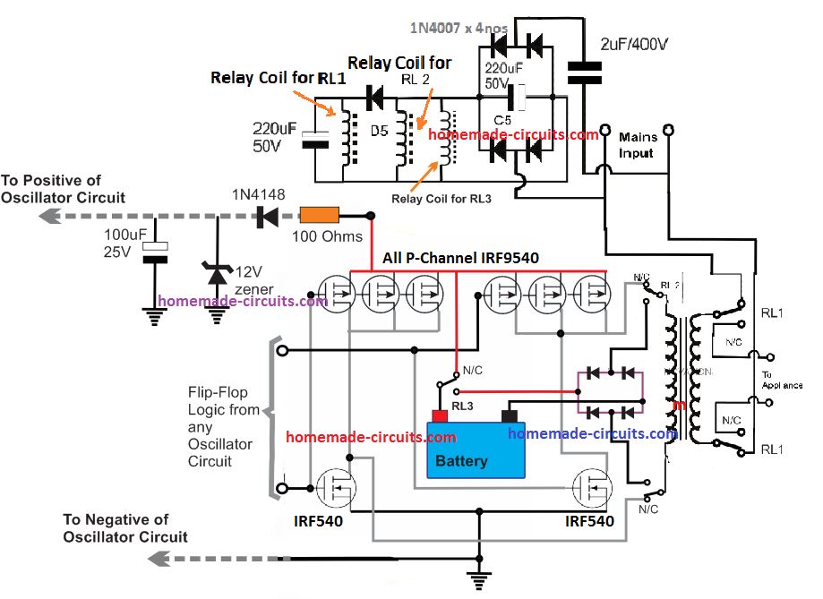
The mini ups circuit diagram has taken the electrical engineering world by storm. It enables you to build ultra-efficient and reliable power supplies for any application - from small home lighting solutions to complex industrial equipment. And it's all thanks to the innovation of mini ups for CFL circuit diagrams.
Invented in the early 1960s, mini ups for CFL circuit diagrams have seen a meteoric rise in popularity ever since. They provide a simple and effective solution for creating reliable power supplies that are both cost-effective and energy efficient. By utilizing a combination of resistors, capacitors, and inductors, mini ups for CFL circuit diagrams can provide a steady and reliable source of power to virtually any application.
The first step to understanding how mini ups for CFL circuit diagrams work is to understand the basic principles of electricity. Electricity is essentially the flow of electrical energy through a conductor and the mini ups circuit diagram is no exception. At its most basic level, the circuit is made up of two components: a power source (usually a battery or solar cell) and the other component, known as the load. The load is the device that will be receiving the electricity. In this case, the load is typically a CFL bulb or other type of fluorescent light.
At the heart of the mini ups for CFL circuit diagram lies the principle of transistors. Transistors act as switches, allowing current to flow between the power source and the load. This current is then regulated and distributed to the load. As the load increases or decreases, the transistor will adjust its resistance accordingly, allowing the amount of current to remain constant.
When the power source is connected to the load, the voltage will decrease as the load uses up more energy. This is where the mini ups for CFL circuit diagram comes into play. By employing capacitors and inductors, the circuit is able to regulate the flow of electricity, ensuring that the load always receives an adequate amount of power.
Using the mini ups for CFL circuit diagram is relatively simple and straightforward. All you need to do is connect the power source and the load, and then connect the transistors. Once the circuit is complete, the transistors will begin regulating the flow of electricity and the load will receive the correct amount of power.
In order to use the mini ups for CFL circuit diagram effectively, it is important to understand the different components and how they work together. Once you have a good understanding of the principles of electricity and the components involved, you should be able to create a reliable and efficient power supply for your project.

Cfl Inverter Kit At Best In Ghaziabad Uttar Pradesh From Home Automation India Pvt Ltd Id 3559189

Convert Your Computer Ups To Home Homemade Circuit Projects

Pdf 270 Mini Electronics Project With Circuit Diagram

Mini Ups System Detailed Circuit Diagram Available

How To Repair Cfl Bulb Lesson Learnt Electronics And Technology News

1 5v To 220v Ac Simple Inverter Envirementalb Com

How Compact Fluorescent Lamps Work And To Dim Them Edn

Make A 1 5v To 220v Inverter Circuit Step By Diy Electronics Projects

Ferrite Core Inverter Circuit Diagram Diy Electronics Projects

Diy Mini Ups For Dsl Modem And Wifi Routers It S Ehtisham

Ferroresonance An Overview Sciencedirect Topics

7 Simple Inverter Circuits You Can Build At Home Homemade Circuit Projects

Use A Cfl Ballast To Drive Leds Edn

3 Simple Dc Ups Circuits For Modem Router Homemade Circuit Projects

Mini Offline Ups Detailed Circuit Diagram Available

Ferrite Core Inverter Circuit Diagram Diy Electronics Projects

Simple 100w Inverter Circuit Working And Diagram Updated

Best Tesla Coil Circuit Diagram

How Compact Fluorescent Lamps Work And To Dim Them Edn
