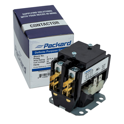
In the modern world, wiring diagrams have come to be a crucial part of understanding how machines and systems work. Whether you’re a professional engineer or an enthusiast looking to understand more about how electrical systems work, learning how to read and interpret a wiring diagram for a Packard C230b Contactor can help you get a handle on the system’s various components and their connections.
From connecting motors to powering up control circuits, a Packard C230b Contactor is often the go-to device for powering up machinery and appliances. Designed to provide accurate, reliable switching and consistent performance, it’s important to understand exactly how a Contactor works by studying its wiring diagram. To help you understand better, let’s take a look at a Packard C230b Contactor’s wiring diagram and what each component means.
The Packard C230b Contactor is made up of two parts: the contactor itself and the electrical connection points. The contactor is the main switch that controls the power that flows from the main source to the load. This is the switch that turns on and off the power supply. The contactor also has a relay coil, which is an electromagnet that changes the flow of electricity. The relay coil is connected to the contactor’s three poles: the middle pole is the common pole, the left pole is the normally open pole, and the right pole is the normally closed pole.
The electrical connection points are the two tabs that attach the contactor to the power source. The top tab is the line side, and the bottom tab is the load side. The line side is where the power source is connected, and the load side is where the device or appliance is connected. Additionally, the contactor has a sensing coil, which senses when the line voltage is too high and trips the contactor, cutting off the power.
Now that you know the parts of the contactor, let’s look at how the wiring diagram works. The diagram will label all the parts, so you can easily identify each one. It’ll also include arrows showing the direction of the current. In addition to that, it’ll include symbols indicating if a switch is normally open or normally closed. Finally, most diagrams will include a legend telling you what each symbol stands for.
Understanding how to read a wiring diagram for a Packard C230b Contactor can help you troubleshoot any issues you might have with the system. By studying the diagram, you can easily identify the source of a problem and quickly make repairs. Now that you know how to read a wiring diagram for a Packard C230b Contactor, you’ll be able to more effectively maintain and troubleshoot your machine.

Packard C230b 2 Pole 30 Amp 120v Vs 240v Control Panel Q A E Herms Brewery Build Forum

E Herms Brewery Build Forum Skrilnetz

Packard C230b Contactor 2 Pole 30 Amps 120 Coil Voltage Com

Hvac Contactors Ul E246810 Temco Controls Ltd
Vertical And Horizontal Power Exhaust
Xmc0 Series

Zooz Zen21 Switch And Whole House Fan Connected Things Smartthings Community
Cs 330 320 300 310 310ies 280 290 620 280ies

Contactor 2 Pole 30 Amps 120 Coil Voltage Packard Online

Kml کنتاکتور خازنی لیفاسا صنعت

Contactor 2 Pole 30 Amps 120 Coil Voltage Packard Online

Definite Purpose Contactor 32a 24 Vac 50 60 Hz Coil Voltage Pn Wdp30 2l Automationdirect
Xmc0 Series

Top 10 Contactor Coil To In 2021 U S A Vasthurengan Com

Electrical Education Electricians Training How To Wire A Time Clock

Modular Contactor Supplier China Etek Electric

I Could Use Some Help Wiring An Electrical Contactor Inline With Existing Temperature Control If Provide All The
Data Sheet Us2 45eg10aja

Question About Wiring Packard C230b Relay

How To Wire A Contactor 8 Steps With Pictures Wikihow
